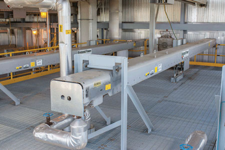
Diamond Power® Boiler Cleaning Equipment
 In 2025, B&W sold its Diamond Power International business to ANDRITZ AG, but the collaboration continues!
Building on the vast experience and knowledge shared over the last century and, most importantly, to provide customers with the most convenient and seamless service, B&W is now a sales representative for Diamond Power equipment in select industries and locations.
Founded in 1903 and headquartered in the United States, Diamond Power International, LLC is a globally recognized leader in advanced boiler cleaning technologies and services. With over 120 years of experience, Diamond Power has a reputation for innovation, reliability, and performance in power generation, pulp & paper, biomass, waste-to-energy and industrial sectors.
As a sales representative, B&W can provide proven, reliable Diamond Power equipment that includes:
- Sootblowers and Intelligent Cleaning Systems
- Water Cleaning Systems
- Drum Level Gauges and Indicators
- High-Performance Cameras and Viewing Systems
- Advanced Sootblowing Controls and Optimization Tools
- Replacement Parts, Upgrades and Rebuilds
- Field Services
[ VISIT ANDRITZ WEBSITE FOR DETAILS ON DIAMOND POWER PRODUCTS & SERVICES ]
Our sales coverage for Diamond Power products includes select customers in utility and industrial markets in the United States, Canada, South America and the Caribbean, Philippines, Vietnam, Indonesia, Algeria, Egypt, Tunisia and Morocco.
Use the form below to connect with us!