The B&W Learning Center
Leading the world in clean power production technology

10 Ways to Minimize Grate Wear in a Waste-to-Energy Boiler
Thermal and mechanical grate wear increases maintenance costs. If the grate is not operated correctly, or if combustion is not properly managed, wear accelerates and there is risk of substantial damage. As a fuel, waste tends to be unpredictable and varies over time. It presents challenges for the plant, and can cause mechanical, thermal and chemical wear.
The good news is there is a way to characterize waste fuel and predict calorific values. Two B&W experts share their experience and offer some suggestions to optimize combustion and minimize grate wear.
1. Conduct at least six grabs per hour
Apart from system control, there are many other factors that allow for stable plant operations and minimal grate wear. Stable operations begin in the waste pit. Truck logistics, storage and mixing must be done right. Even how the grab opens when filling the hopper is important.
Conduct at least six grabs of waste per hour and make sure the size of the fuel fits the chute, so that "hangers" are avoided. Hangers refer to material stuck in the chute and can cause backfire directly in the chute. If the process of getting the fuel on the grate is not managed properly, plant operations will be unstable. Instability wears out mechanical parts.
2. Maintain steady fuel feeding
It is important that fuel is fed onto the grate in a steady flow with as few rapid variations as possible. Feeding and grate movement must be slow and at the right speeds. The correct distribution of speed levels between each grate section should be applied.
3. Keep the feeding hopper and slag pusher airtight
If the feeding hopper and slag pusher are not airtight, it is difficult to control the combustion process and suction fan.
Low water level in the slag pusher, or large objects in the shaft will puncture negative pressure in the furnace. Control of the combustion process will subsequently be lost.
4. Keep the chute filled with waste
If the waste level and compression in the chute is too low, there is a risk of creating an avalanche effect in the chute. This can lead to large chunks of fuel calving onto the grate which results in substantial fluctuations. This in turn causes mechanical components associated with combustion and the grate to get into extreme positions, thus increasing wear.
5. Maintain balance between the controllers
The control system must be tuned so there is a balance between the regulators. Optimum combustion control can be achieved when O2 percentage, temperatures and steam production are all stable.
It these parameters are met, grate and pusher wear will be minimized, while also reducing emissions and fuel consumption, minimizing unburned slag, experience fewer alarms, and lower the risk of unplanned stops.
Furthermore, stable combustion combined with our VolumixTM system allows for optimal SNCR conditions.
6. Adjust the fuel layer
The combustion process is primarily controlled by four parameters: (a) grate speed, (b) distribution of primary air under the grate, (c) proportion of primary and secondary air, and (d) air preheating.
If the fuel layer is thin, the reaction intensity is enhanced, and the combustion zone will move higher up on the grate.
The properties of the fuel vary from plant to plant. Many parameters affect the fuel: season, fuel source, sorting, shredding, etc.
The height of the fuel layer is mainly controlled by the difference between the speed of the feeding pusher and the speed of the grate. The relationship between the speed of the feeding pusher and the first grate determines whether the grate layer rises or falls.
If the fuel layer has a large and porous surface (allowing for better pyrolysis and oxidation), then combustion will be faster (compared to a compact and dense fuel).
The height of the fuel layer must be adapted to the individual fuel types or fractions. A wet and dense fuel requires a relatively low layer while a light fuel requires a high layer.
If the fuel layer becomes too high, the amount of unburned material in the slag can increase.
A low fuel layer provides a small buffer of fuel on the grate, and small variations in the fuel can lead to large variations in energy production.
If the layer is smaller, the combustion reaction rate increases and the combustion zone moves up the grate.
When the grate is exposed, it faces direct radiation and flue gas, thus increasing grate wear.

Grate speed is too low. The fuel layer rises and unburned material rolls down the slag chute.

Grate speed is too high. The fuel layer is pulled apart. Holes are formed and partially burned items are transported to the slag chute.
7. Base air distribution on the fuel
The distribution of primary air under the grate must be adapted to the fuel. If the fuel has a low reaction rate, add primary air at an early phase of the grate.
Preheating the combustion air increases the activity in the drying zone and combustion zone. With higher water content, there is an increased need for higher preheating temperature. Preheating causes the fuel to dry faster and allows for an easier combustion process. More preheating causes the combustion zone to move up the grate.
8. Cover the T-plates
When burning household waste on a DynaGrate® combustion grate, the fuel layer should just cover the T-plates by the flame. This ensures a lower amount of unburned material in the slag.
A low amount of excess air increases the thermal efficiency of the plant, but too little excess air can lead to slag formation. A low amount of excess air will also lead to unburned material in the slag and higher CO emissions.

9. Do not operate water-cooled grates without cooling
If the grate is water-cooled, knowledge of installation and operation is essential to avoid grate damage.
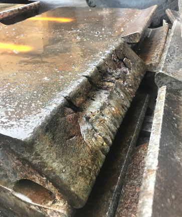
Operation without cooling water for even for a short time can lead to damage. It is very important that operators are alert and respond quickly to any alarms.
A supplement for the grate cooling control system is available which provides improved equipment protection. We can demonstrate how this could be applied at your plant.

A water-cooled DynaGrate element after operation without water-cooling for only a short while.
10. Ask us if you want to know more
If you are experiencing any of these issues or have questions about proper operation of your waste-fired grate, perhaps your plant would benefit from a visit from our service team. We can also connect remotely to your control system data, so we can help you with data analysis.