The B&W Learning Center
Leading the world in clean power production technology
A Modeling Example for Sorbent Injection Systems

A Numerical Modeling Example – Sorbent Injection Systems
Situation
There are two common types of dry sorbents that are injected in the flue upstream of a particle collection system to control emissions. Dry alkali particles (trona, sodium bicarbonate or hydrated lime) are injected to remove acid gases such as sulfur dioxide (SO2), hydrogen chloride (HCl), sulfur trioxide (SO3) and sulfuric acid (H2SO4) from the flue gas.
Powdered activated carbon (PAC) particles are injected to remove mercury and other toxic compounds. Sorbent injection has a low capital cost, but can be high in reagent cost if improperly designed.
To minimize the amount of sorbent used, it must be injected into the flue with a properly engineered lance that effectively disperses it into the gas, and the flow conditions in the flue must be sufficient for the particles to stay suspended for the required residence time to complete the desired absorption. The particle collection device also allows for longer contact time between solids and gas for reactions to occur.
Analysis
Numerical flow modeling is used to simulate a dry sorbent injection system. The model includes all the flue work, starting upstream of the injection lances, and continuing to the inlet of the particulate collector. The arrangement of flue work is generally site specific which makes each application unique. Velocity, temperature and species concentration distributions at the model inlet can be specified as uniform or can be based on field measurements if available. The flow distribution throughout the flue work is generally predicted for full load conditions.
Alternative cases can then be investigated by making use of flow modification devices (i.e., turning vanes, flow splitters, baffle plates, and perforated plates) to improve the characteristics of the flow, specifically at the dry sorbent injection location, and to minimize flow recirculation and dead zones where particles can be trapped or drop out. Nozzle design and arrangement are investigated to maximize particle dispersion at the injection location. Particles are injected and tracked to determine distribution at various downstream locations in the flue. In this analysis the particles do not chemically react with the gas. Reaction models can also be used to enhance the overall analysis of system performance.
Results
The gas flow through the flue is simulated with the trajectories of millions of particles to determine the statistical distribution of particles.
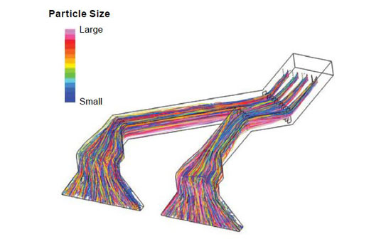
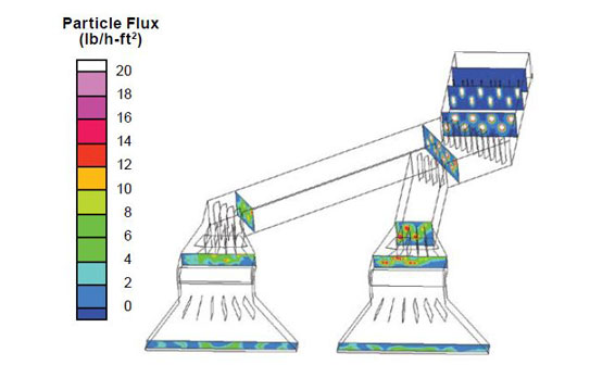
Fig. 1 shows trajectories in the flue throughout the entire model. The color of each trajectory denotes the size of the particle. Larger particles have more momentum and penetrate further as they leave the nozzle, and they also settle to the bottom faster as they move through the flue. Fig. 2 shows particle flux distribution at specified planes as a measure of dispersion and mixing with the gas.
Equipment designers use these results to optimize the number and arrangement of lances to achieve the most uniform distribution in the flue and effective absorption of the targeted gas-phase reactant.

Fig. 1 Numerical modeling results for a section of flue showing sorbent particle trajectories colored by particle size.

Fig. 2 Contours of sorbent particle mass flux at selected planes of flue corresponding to Fig. 1.