The B&W Learning Center
Leading the world in clean power production technology
Wet FGD Spray Headers

Upgrades to Wet FGD Absorber Spray Headers
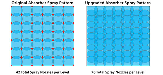
Many wet FGD absorber modules were originally designed with spray patterns which do not maximize contact of the flue gas with the slurry spray. Older designs have gaps or openings in the spray pattern that allow flue gas to bypass the spray zones without contacting the slurry. Many of these gaps are on the outside of the absorber near the absorber walls. These gaps provide a direct path for the flue gas to bypass the slurry spray.
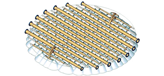
Figures 1 is an example of an original spray pattern compared to an upgraded spray pattern design in the same absorber. The red areas in the original design indicate areas with no spray coverage. To achieve complete coverage, the modifications shown in the figure on the right involved replacement of the spray headers and nozzles. Modifications to the absorber pumps and absorber discharge pumping were not necessary to realize the benefit of the spray pattern redesign. Figure 2 illustrates B&W’s spray header design which provides complete coverage across the entire absorber tower.

Figure 1 – Original spray pattern compared to an upgraded spray pattern design in the same absorberFigure 1 – Original spray pattern compared to an upgraded spray pattern design in the same absorber